Stroking and Filling Graphics Primitives
You already know how to create different geometric primitives and more complicated shapes. This lesson teaches how to add some color and fancy outlines to your graphics and represents filling and stroking:
- Filling – is a process of painting the shape’s interior with solid color or a color gradient, or a texture pattern
- Stroking – is a process of drawing a shape’s outline applying stroke width, line style, and color attribute
To apply fancy line styles and fill patterns to geometric primitives change
the stroke and paint attributes in the
Graphics2D context before rendering. For
example, draw a dashed line by creating an appropriate
Stroke object. To add this stroke to the Graphics2D context before
you render the line call the setStroke method .
Similarly, you apply a gradient fill to a Shape object by
creating a GradientPaint object and adding it to the
Graphics2D context.
The following code lines enrich geometric primitives with filling and stroking context:
// draw RoundRectangle2D.Double

final static float dash1[] = {10.0f};
    final static BasicStroke dashed = new BasicStroke(1.0f,
                                          BasicStroke.CAP_BUTT,
                                          BasicStroke.JOIN_MITER,
                                          10.0f, dash1, 0.0f);
g2.setStroke(dashed);
g2.draw(new RoundRectangle2D.Double(x, y,
                                   rectWidth,
                                   rectHeight,
                                   10, 10));
// fill Ellipse2D.Double
redtowhite = new GradientPaint(0,0,color.RED,100, 0,color.WHITE);
g2.setPaint(redtowhite);
g2.fill (new Ellipse2D.Double(0, 0, 100, 50));
The
ShapesDemo2D.java code example represents additional implementations of stoking and filling.
Defining Fancy Line Styles and Fill Patterns
Using the Java 2D™ Stroke and Paint classes, you can define fancy line styles and fill patterns.
Line Styles
Line styles are defined by the stroke attribute in the
Graphics2D rendering context. To set the stroke attribute,
you create a BasicStroke object and pass it into the
Graphics2D setStroke method.
A BasicStroke object holds information about the line
width, join style, end-cap style, and dash style. This information is
used when a Shape is rendered with the draw
method.
The line width
is the thickness of the line measured perpendicular to its trajectory.
The line width is specified as a float value in user
coordinate units, which are roughly equivalent to 1/72 of an inch when the
default transform is used.
The join style
is the decoration that is applied where two line segments meet.
BasicStroke supports the following three join styles:
![]()
JOIN_BEVEL
![]()
JOIN_MITER
![]()
JOIN_ROUND
The end-cap style
is the decoration that is applied where a line segment ends.
BasicStroke supports the following three end-cap styles:
![]()
CAP_BUTT
![]()
CAP_ROUND
![]()
CAP_SQUARE
The dash style defines the pattern of opaque and transparent sections applied along the length of the line. The dash style is defined by a dash array and a dash phase. The dash array defines the dash pattern. Alternating elements in the array represent the dash length and the length of the space between dashes in user coordinate units. Element 0 represents the first dash, element 1 the first space, and so on. The dash phase is an offset into the dash pattern, also specified in user coordinate units. The dash phase indicates what part of the dash pattern is applied to the beginning of the line.
Fill Patterns
Fill patterns are defined by the paint attribute in theGraphics2D rendering context. To set the paint attribute,
you create an instance of an object that implements the
Paint interface and pass it into the
Graphics2D setPaint method.
The following three classes implement the Paint interface:
Color, GradientPaint, and
TexturePaint.
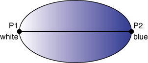
To create a GradientPaint,
you specify a beginning position and color and an ending position and
color. The gradient changes proportionally from one color to the other color
along the line connecting the two positions. For example:

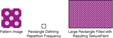
The pattern for a TexturePaint class
is defined by a BufferedImage class.
To create a TexturePaint object,
you specify the image that contains the pattern and a rectangle that
is used to replicate and anchor the pattern.
The following image represents this feature:

